Hongtelecom equipment service Limited ( Hong Telecom ) would like to show you : how to Replace an SCC Board of Huawei OptiX OSN 9800. ( Take TN52SCC for an example )
Setting the Jumper on the SCC
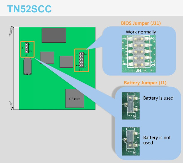
This topic describes how to set the battery jumpers and BIOS jumpers on the spare SCC board before replacing the SCC board.
The battery jumpers on the SCC help ensure that the configuration is maintained upon a power failure of the SCC. If the board is in use, place a jumper cap over the battery jumper to make a short circuit, which allows the battery to supply power normally.
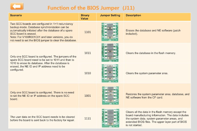
The BIOS jumpers help clear the system parameter area and database in the flash memory on the SCC board. Figure 1 shows the functions of the BIOS jumpers.
Replacing the SCC Board in a Master Subrack with SCC 1+1 Protection
This topic describes how to replace the SCC board in a master subrack when SCC 1+1 protection is configured.
Prerequisites
- You are an NMS user with "Administrators" privilege.
- The SCC replacement board is of the same type as the SCC board to be replaced.
- The battery jumpers on the spare board are correctly set before the board replacement.
Impact on the System
Replacing an SCC board configured with 1+1 protection does not affect the existing services.
During board replacement, the following alarms may be reported: COMMUN_FAIL, BD_LEDTEST, BD_STATUS, HARD_ERR, SYNC_FAIL, WRG_BD_TYPE, SWDL_PKG_NOBDSOFT, SWDL_CHGMNG_NOMATCH, SWDL_BD_NOT_MATCH, SCC_CHANGE. These alarms do not affect services and will be cleared after board replacement is completed.
The SCC_CHANGE alarm reminds the user that the SCC board has been replaced. After the replacement, the data on the current SCC board might be inconsistent with the data on the original SCC board, and the NE will enter into the configuration lockout state. As a result, new service information cannot be downloaded. If the services on the current SCC board are forcibly downloaded, the existing services before the replacement might be lost. Check whether the SCC board replacement is necessary.
- If the SCC board replacement is necessary, add and then delete any logical board of the NE on the NMS. The alarm is automatically cleared.
- If the SCC board is replaced by mistake, insert the original SCC board back.
For SCC 1+1 protection, replacing one of the SCC in the protection group does not interrupt communication between the NE where the SCC board resides and the U2000 after you switch services from one SCC board to the other SCC board.
Precautions
During the SCC board replacement, do not configure services on the NE before the new SCC board is started up.
Procedure
- Select a spare SCC board as the replacement board. Ensure that the spare SCC board and the SCC board to be replaced have the same name and are of the same type.
 NOTE:
The jumper inside the board is used to enable or disable the power supply from the battery. The battery is fixed on the board and cannot be replaced. If the replacement board is not used, cap pins 1 and 2 of the jumper. If the replacement board is in service, cap pins 2 and 3. The standard voltage of the battery is 3.6 V. Use a multimeter to measure the battery voltage. If the voltage is lower than 3 V, it indicates that the battery is not working. In this case, select a new replacement board.
- Query and record the current alarms on the NE.
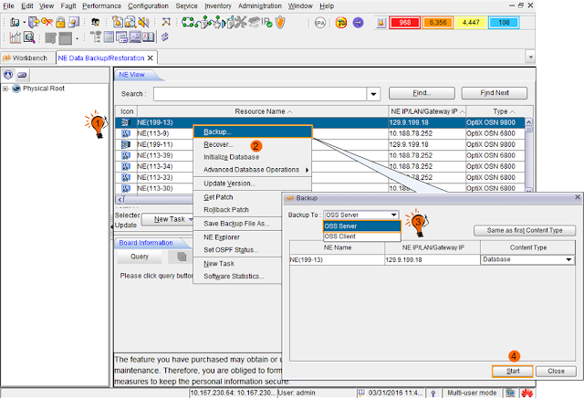
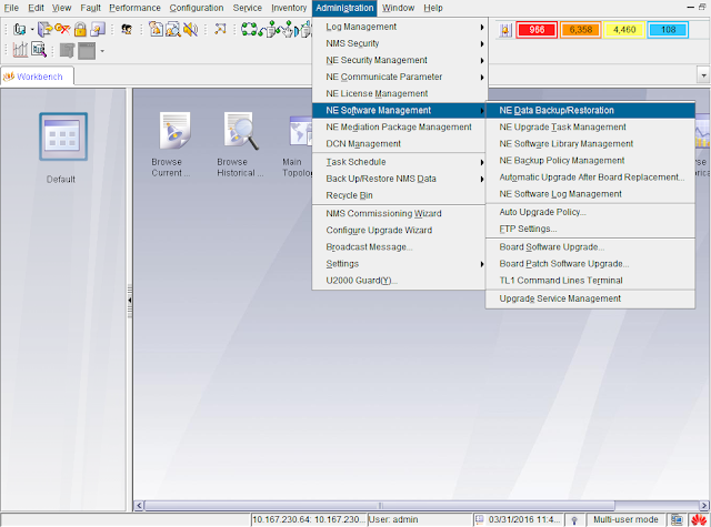
- Back up the NE database to the NMS server. This is to record the NE database for future reference.
- Follow the steps below to review the working state of the board to be replaced.
- In the NE Explorer, click the NE and choose from the Function Tree.
- Click Query.
- If the board to be replaced is the active board, go to 6. Otherwise, go to 7.
- If the board to be replaced is the active board, complete the following the steps to perform an active/standby switchover on the U2000. After active/standby switching is completed, NE data must be manually uploaded. The following uses an Active Board that is the Working Board as an example to describe how to perform an active/standby switchover.
- In the Main Topology, right-click the desired NE and click NE Explorer from the shortcut menu. The NE Explorer window is displayed.
- Choose from the Function Tree.
- Right-click the desired SCC Board 1+1 Protection. Select Working/Protection Switching from the shortcut menu. Click OK in the window displayed.
- Click Query. If the Active Board is not the board to be replaced, the switching is successful.
- Query the alarms and performance events on the U2000. Check if services are normal. If services are normal, there must be no new abnormal alarms or performance events, and the switching is successful.
- On the NMS, enable the removal indication function for the board to be replaced.
- In the NE Explorer, select the desired NE and choose in the navigation tree.
- Select the desired board. Double-click Enable Indication and set it to Enabled.
- Click Apply.
- Click Query to confirm that the function is successfully enabled.
 NOTE:
After the removal indication function is enabled for the board to be replaced, the STAT indicator on the board slowly blinks green and Minor alarm indicator in the subrack slowly blinks yellow so that the onsite maintenance engineer can easily locate the board to be replaced.
- Inform the onsite maintenance engineer and replace the board. For details about how to remove a board, see Procedure of Replacing a Board.
- View the indicators on the front panel of the new board. After the board is inserted, it takes about 60 minutes for the board to complete database synchronization. During the synchronization period, the board indicators change as described below. If the indicator gives an abnormal indication, you need to reinsert the board or select a new replacement board. For details about the indicators, see Board Indicators.
- The board will run properly 3 to 5 minutes later after it is inserted. When the board is running properly, the LED indicator (PWR) on the front panel of the board starts to display.
- Then PROG indicator is blinking green quickly, indicating that the configuration synchronization is being performed between the active and standby boards. The synchronization duration depends on the size of the NE database, and longer synchronization duration is required for a larger NE database. After the configuration synchronization is completed, the inserted board is automatically reset. The PROG indicator on the inserted board is steady green. The STAT indicator is blinking slowly.
- If the board removal indication function is enabled before board replacement, disable this function on the U2000 after the board replacement is complete.
- In the NE Explorer, select the desired NE and choose in the navigation tree.
- Select the desired board and set Enable Indication to Disabled.
- Click Apply.
- Click Query to confirm that the function is successfully disabled.
- Optional: If a switchover between the active and standby SCC boards has been performed before board replacement, follow the steps below to restore the active/standby status of the SCC boards back to the original status.
- Check and set the other parameters on the U2000 to ensure that the parameter values of the new board are the same as the original data.
- Check the software information of the new system control board against the original data.
- Synchronize the NE time with the NMS server time.
- Check the NE alarm attribute data against the original data. The data include saving mode, mask mode, reversion mode and delayed report.
- Check the alarm suppression setting data against the original data.
- Enable the NE performance monitoring.
- Query the current alarms of the NE by using the U2000.
- In the Main Topology view, choose from the Main Menu.
- Click the Basic Setting and Alarm Source tabs in turn on the Filter dialog box to set the filter conditions for the current alarms.
- Click OK.
- Record the current alarms of the NE.
The jumper inside the board is used to enable or disable the power supply from the battery. The battery is fixed on the board and cannot be replaced. If the replacement board is not used, cap pins 1 and 2 of the jumper. If the replacement board is in service, cap pins 2 and 3. The standard voltage of the battery is 3.6 V. Use a multimeter to measure the battery voltage. If the voltage is lower than 3 V, it indicates that the battery is not working. In this case, select a new replacement board.
- In the NE Explorer, click the NE and choose from the Function Tree.
- Click Query.
- In the Main Topology, right-click the desired NE and click NE Explorer from the shortcut menu. The NE Explorer window is displayed.
- Choose from the Function Tree.
- Right-click the desired SCC Board 1+1 Protection. Select Working/Protection Switching from the shortcut menu. Click OK in the window displayed.
- Click Query. If the Active Board is not the board to be replaced, the switching is successful.
- Query the alarms and performance events on the U2000. Check if services are normal. If services are normal, there must be no new abnormal alarms or performance events, and the switching is successful.
- In the NE Explorer, select the desired NE and choose in the navigation tree.
- Select the desired board. Double-click Enable Indication and set it to Enabled.
- Click Apply.
- Click Query to confirm that the function is successfully enabled.
After the removal indication function is enabled for the board to be replaced, the STAT indicator on the board slowly blinks green and Minor alarm indicator in the subrack slowly blinks yellow so that the onsite maintenance engineer can easily locate the board to be replaced.
- The board will run properly 3 to 5 minutes later after it is inserted. When the board is running properly, the LED indicator (PWR) on the front panel of the board starts to display.
- Then PROG indicator is blinking green quickly, indicating that the configuration synchronization is being performed between the active and standby boards. The synchronization duration depends on the size of the NE database, and longer synchronization duration is required for a larger NE database. After the configuration synchronization is completed, the inserted board is automatically reset. The PROG indicator on the inserted board is steady green. The STAT indicator is blinking slowly.
- In the NE Explorer, select the desired NE and choose in the navigation tree.
- Select the desired board and set Enable Indication to Disabled.
- Click Apply.
- Click Query to confirm that the function is successfully disabled.
- Check the software information of the new system control board against the original data.
- Synchronize the NE time with the NMS server time.
- Check the NE alarm attribute data against the original data. The data include saving mode, mask mode, reversion mode and delayed report.
- Check the alarm suppression setting data against the original data.
- Enable the NE performance monitoring.
- In the Main Topology view, choose from the Main Menu.
- Click the Basic Setting and Alarm Source tabs in turn on the Filter dialog box to set the filter conditions for the current alarms.
- Click OK.
- Record the current alarms of the NE.
Replacing the SCC Board in a Slave Subrack
This section describes how to replace an SCC board in a slave subrack.
This section describes how to replace an SCC board in a slave subrack.
Prerequisites
Impact on the System
During board replacement, the following alarms may be reported: . These alarms do not affect services and will be cleared after board replacement is completed.
The SCC_CHANGE alarm reminds the user that the SCC board has been replaced. After the replacement, the data on the current SCC board might be inconsistent with the data on the original SCC board, and the NE will enter into the configuration lockout state. As a result, new service information cannot be downloaded. If the services on the current SCC board are forcibly downloaded, the existing services before the replacement might be lost. Check whether the SCC board replacement is necessary.
- If the SCC board replacement is necessary, add and then delete any logical board of the NE on the NMS. The alarm is automatically cleared.
- If the SCC board is replaced by mistake, insert the original SCC board back.
Replacing the SCC does not affect the existing services.
If the SCC is configured with 1+1 protection, replacing the SCC does not affect the system.
If an SCC is not configured with 1+1 protection, replacing the SCC has the following effects:
- The fan is automatically changed to the "High Speed" mode.
- The ESC and OSC communication of the subrack where the replacement SCC resides fails.
- The POWER_FAIL alarm of the subrack where the replacement SCC resides cannot be reported.
- The subrack whose ID conflicts with the ID of the subrack where the replacement SCC resides cannot be detected.
- Certain optical boards in the slave subrack housing the SCC board to be replaced go offline and cannot be managed. However, the services on these boards are not affected.
Tools, Equipment, and Materials
Procedure
- Select a spare board. Ensure that the name, and the type of the spare board are the same as those of the original board.
 NOTE:
The jumper inside the board is used to enable or disable the power supply from the battery. The battery is fixed on the board and cannot be replaced. If the replacement board is not used, cap pins 1 and 2 of the jumper. If the replacement board is in service, cap pins 2 and 3. The standard voltage of the battery is 3.6 V. Use a multimeter to measure the battery voltage. If the voltage is lower than 3 V, it indicates that the battery is not working. In this case, select a new replacement board.
- Query and record the current NE alarms.
- On the NMS, enable the removal indication function for the board to be replaced.
- In the NE Explorer, select the desired NE and choose in the navigation tree.
- Select the desired board. Double-click Enable Indication and set it to Enabled.
- Click Apply.
- Click Query to confirm that the function is successfully enabled.
 NOTE:
After the removal indication function is enabled for the board to be replaced, the STAT indicator on the board slowly blinks green and Minor alarm indicator in the subrack slowly blinks yellow so that the onsite maintenance engineer can easily locate the board to be replaced.
- Instruct the onsite maintenance engineers to replace the board. For more information regarding how to replace a board, refer to Procedure of Replacing a Board.
- Check the indicators of the new board. It takes five minutes for a new board to work normally after insertion. After the board works normally, the PROG indicator will be steady green. If the indicator gives an abnormal indication, reinsert the board, or replace the board again. For more information regarding indicator definitions, refer to "Board Indicators".
- Optional: If the SCC board is configured with 1+1 protection, and the board removal indication function is enabled before board replacement, disable this function on the U2000 after the board replacement is complete.
- In the NE Explorer, select the desired NE and choose in the navigation tree.
- Select the desired board and set Enable Indication to Disabled.
- Click Apply.
- Click Query to display the operation result. Verify that the function is successfully enabled.
- Query the current alarms of the NE by using the U2000.
- In the Main Topology view, choose from the Main Menu.
- Click the Basic Setting and Alarm Source tabs in turn on the Filter dialog box to set the filter conditions for the current alarms.
- Click OK.
- Record the current alarms of the NE.
Below are DWDM equipment huawei SCC boards series:
03030JVX TN51SCC01
03021CGE TN16SCC
03030LNB TN52SCC01
03030JBK TN22SCC01
03030CBF TN11SCC01
03030EUK TN21SCC01
03020PSF TNK2SCC
As a world leading Huawei networking products supplier, Hong Telecom Equipment Service LTD(HongTelecom) keeps regular stock of Huawei router and switch and all cards at very good price, also HongTelecom ship to worldwide with very fast delivery.
For related articles, visit the HongTelecom Blog and HongTelecom Blogger.
For real pictures of related product, visit the HongTelecom Gallery.
To buy related product, visit the HongTelecom Online Shop.
- Select a spare board. Ensure that the name, and the type of the spare board are the same as those of the original board.
NOTE:
The jumper inside the board is used to enable or disable the power supply from the battery. The battery is fixed on the board and cannot be replaced. If the replacement board is not used, cap pins 1 and 2 of the jumper. If the replacement board is in service, cap pins 2 and 3. The standard voltage of the battery is 3.6 V. Use a multimeter to measure the battery voltage. If the voltage is lower than 3 V, it indicates that the battery is not working. In this case, select a new replacement board. - Query and record the current NE alarms.
- On the NMS, enable the removal indication function for the board to be replaced.
- In the NE Explorer, select the desired NE and choose in the navigation tree.
- Select the desired board. Double-click Enable Indication and set it to Enabled.
- Click Apply.
- Click Query to confirm that the function is successfully enabled.
NOTE:
After the removal indication function is enabled for the board to be replaced, the STAT indicator on the board slowly blinks green and Minor alarm indicator in the subrack slowly blinks yellow so that the onsite maintenance engineer can easily locate the board to be replaced. - Instruct the onsite maintenance engineers to replace the board. For more information regarding how to replace a board, refer to Procedure of Replacing a Board.
- Check the indicators of the new board. It takes five minutes for a new board to work normally after insertion. After the board works normally, the PROG indicator will be steady green. If the indicator gives an abnormal indication, reinsert the board, or replace the board again. For more information regarding indicator definitions, refer to "Board Indicators".
- Optional: If the SCC board is configured with 1+1 protection, and the board removal indication function is enabled before board replacement, disable this function on the U2000 after the board replacement is complete.
- In the NE Explorer, select the desired NE and choose in the navigation tree.
- Select the desired board and set Enable Indication to Disabled.
- Click Apply.
- Click Query to display the operation result. Verify that the function is successfully enabled.
- Query the current alarms of the NE by using the U2000.
- In the Main Topology view, choose from the Main Menu.
- Click the Basic Setting and Alarm Source tabs in turn on the Filter dialog box to set the filter conditions for the current alarms.
- Click OK.
- Record the current alarms of the NE.
Below are DWDM equipment huawei SCC boards series:
| 03030JVX | TN51SCC01 |
| 03021CGE | TN16SCC |
| 03030LNB | TN52SCC01 |
| 03030JBK | TN22SCC01 |
| 03030CBF | TN11SCC01 |
| 03030EUK | TN21SCC01 |
| 03020PSF | TNK2SCC |
As a world leading Huawei networking products supplier, Hong Telecom Equipment Service LTD(HongTelecom) keeps regular stock of Huawei router and switch and all cards at very good price, also HongTelecom ship to worldwide with very fast delivery.
For related articles, visit the HongTelecom Blog and HongTelecom Blogger.
For real pictures of related product, visit the HongTelecom Gallery.
To buy related product, visit the HongTelecom Online Shop.


HP DL380 Gen9 Rack Server in UAE, Proliant 2U Rack Server in UAE, Rack Server in UAE
ReplyDeletehttps://gccgamers.com/hp-dl380.html
HP DL380 Gen9 Rack Server in UAE, Safe Shopping Multiple Payment Options Express Delivery GCC Gamers Moneyback Guarantee.
1634522692595-15